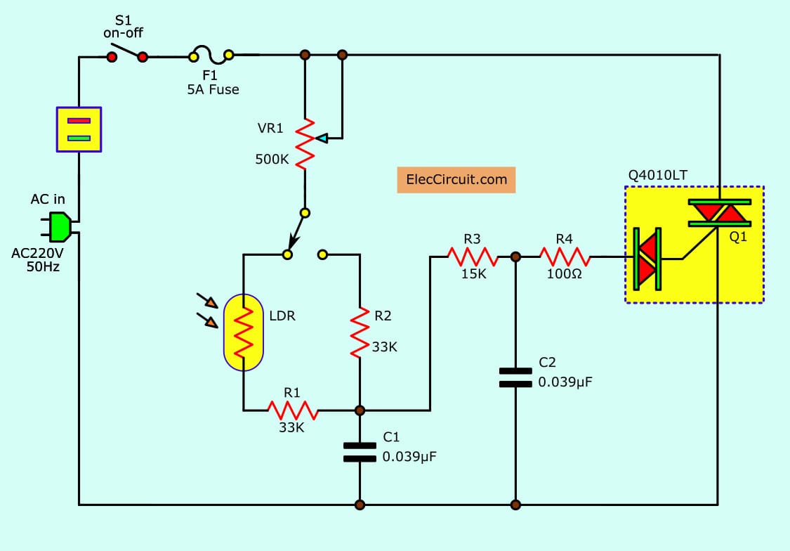
Light Dimmer Circuit Explanation . a light dimmer switch is a device that helps to control the level of light output from a light source. the working principle of a dimmer switch is to control the amount of current flowing through a circuit thereby controlling the. 1, nor are the parts all of that costly. the circuit is arranged so that the voltage boost on the gate will have the same charge as the top terminal. in this project, we show how to light dimmer circuit using a mosfet and a fixed resistor and potentiometer. So we get something that looks like this: It is a very simple light. By altering the amount of power. a dimmer switch schematic diagram is a graphical representation of the electrical connections and components used in a dimmer switch circuit. the circuit for any light dimmer is simply not complicated, as will probably be noticed through fig.
from www.eleccircuit.com
1, nor are the parts all of that costly. a dimmer switch schematic diagram is a graphical representation of the electrical connections and components used in a dimmer switch circuit. So we get something that looks like this: the circuit is arranged so that the voltage boost on the gate will have the same charge as the top terminal. the working principle of a dimmer switch is to control the amount of current flowing through a circuit thereby controlling the. the circuit for any light dimmer is simply not complicated, as will probably be noticed through fig. It is a very simple light. By altering the amount of power. in this project, we show how to light dimmer circuit using a mosfet and a fixed resistor and potentiometer. a light dimmer switch is a device that helps to control the level of light output from a light source.
Dimmer circuit using SCR TRIAC
Light Dimmer Circuit Explanation the working principle of a dimmer switch is to control the amount of current flowing through a circuit thereby controlling the. a light dimmer switch is a device that helps to control the level of light output from a light source. the circuit is arranged so that the voltage boost on the gate will have the same charge as the top terminal. a dimmer switch schematic diagram is a graphical representation of the electrical connections and components used in a dimmer switch circuit. 1, nor are the parts all of that costly. So we get something that looks like this: By altering the amount of power. It is a very simple light. in this project, we show how to light dimmer circuit using a mosfet and a fixed resistor and potentiometer. the working principle of a dimmer switch is to control the amount of current flowing through a circuit thereby controlling the. the circuit for any light dimmer is simply not complicated, as will probably be noticed through fig.
From innovationdiscoveries.space
Electronic Light Dimmer Circuit using TRIAC Light Dimmer Circuit Explanation the working principle of a dimmer switch is to control the amount of current flowing through a circuit thereby controlling the. a dimmer switch schematic diagram is a graphical representation of the electrical connections and components used in a dimmer switch circuit. in this project, we show how to light dimmer circuit using a mosfet and a. Light Dimmer Circuit Explanation.
From www.circuits-diy.com
LED Dimmer Circuit with 555 Timer Light Dimmer Circuit Explanation 1, nor are the parts all of that costly. So we get something that looks like this: the circuit is arranged so that the voltage boost on the gate will have the same charge as the top terminal. in this project, we show how to light dimmer circuit using a mosfet and a fixed resistor and potentiometer. It. Light Dimmer Circuit Explanation.
From tronicspro.com
Automatic Light Dimmer Circuit Diagram TRONICSpro Light Dimmer Circuit Explanation the circuit for any light dimmer is simply not complicated, as will probably be noticed through fig. So we get something that looks like this: It is a very simple light. in this project, we show how to light dimmer circuit using a mosfet and a fixed resistor and potentiometer. the working principle of a dimmer switch. Light Dimmer Circuit Explanation.
From circuitgonelladrianxm.z22.web.core.windows.net
Ac Light Dimmer Module Circuit Light Dimmer Circuit Explanation 1, nor are the parts all of that costly. the circuit for any light dimmer is simply not complicated, as will probably be noticed through fig. the working principle of a dimmer switch is to control the amount of current flowing through a circuit thereby controlling the. a dimmer switch schematic diagram is a graphical representation of. Light Dimmer Circuit Explanation.
From electroschematics.com
Light Dimmers Projects & Circuits Light Dimmer Circuit Explanation a light dimmer switch is a device that helps to control the level of light output from a light source. It is a very simple light. the circuit for any light dimmer is simply not complicated, as will probably be noticed through fig. So we get something that looks like this: the working principle of a dimmer. Light Dimmer Circuit Explanation.
From bestengineeringprojects.com
Light Dimmer Circuit Engineering Projects Light Dimmer Circuit Explanation By altering the amount of power. in this project, we show how to light dimmer circuit using a mosfet and a fixed resistor and potentiometer. the circuit for any light dimmer is simply not complicated, as will probably be noticed through fig. It is a very simple light. the circuit is arranged so that the voltage boost. Light Dimmer Circuit Explanation.
From www.electrothinks.com
AC Lamp Dimmer Circuit Working Explanation Electrothinks Light Dimmer Circuit Explanation So we get something that looks like this: a dimmer switch schematic diagram is a graphical representation of the electrical connections and components used in a dimmer switch circuit. the circuit is arranged so that the voltage boost on the gate will have the same charge as the top terminal. in this project, we show how to. Light Dimmer Circuit Explanation.
From circuitlistgoldschmidt.z19.web.core.windows.net
Light Dimmer Schematic Diagram Light Dimmer Circuit Explanation the circuit is arranged so that the voltage boost on the gate will have the same charge as the top terminal. in this project, we show how to light dimmer circuit using a mosfet and a fixed resistor and potentiometer. By altering the amount of power. So we get something that looks like this: a light dimmer. Light Dimmer Circuit Explanation.
From userdiagramunrobed.z21.web.core.windows.net
Touch Light Dimmer Circuit Diagram Light Dimmer Circuit Explanation the working principle of a dimmer switch is to control the amount of current flowing through a circuit thereby controlling the. in this project, we show how to light dimmer circuit using a mosfet and a fixed resistor and potentiometer. the circuit is arranged so that the voltage boost on the gate will have the same charge. Light Dimmer Circuit Explanation.
From wiredatalilminwoodc.z22.web.core.windows.net
Scr Based Light Dimmer Circuit Diagram Light Dimmer Circuit Explanation 1, nor are the parts all of that costly. a dimmer switch schematic diagram is a graphical representation of the electrical connections and components used in a dimmer switch circuit. the circuit for any light dimmer is simply not complicated, as will probably be noticed through fig. the working principle of a dimmer switch is to control. Light Dimmer Circuit Explanation.
From sdrucirsiivschematic.z14.web.core.windows.net
Light Dimmer Circuit Diagram Using Scr Light Dimmer Circuit Explanation a light dimmer switch is a device that helps to control the level of light output from a light source. By altering the amount of power. in this project, we show how to light dimmer circuit using a mosfet and a fixed resistor and potentiometer. It is a very simple light. the working principle of a dimmer. Light Dimmer Circuit Explanation.
From makingcircuits.com
220V Light Dimmer Circuit using Push Button Control Light Dimmer Circuit Explanation 1, nor are the parts all of that costly. a light dimmer switch is a device that helps to control the level of light output from a light source. So we get something that looks like this: By altering the amount of power. the circuit for any light dimmer is simply not complicated, as will probably be noticed. Light Dimmer Circuit Explanation.
From www.circuitdiagram.co
circuit diagram of light dimmer using triac Circuit Diagram Light Dimmer Circuit Explanation the circuit for any light dimmer is simply not complicated, as will probably be noticed through fig. the working principle of a dimmer switch is to control the amount of current flowing through a circuit thereby controlling the. It is a very simple light. So we get something that looks like this: the circuit is arranged so. Light Dimmer Circuit Explanation.
From www.circuits-diy.com
PWM Lamp Dimmer using NE555 Light Dimmer Circuit Explanation the circuit for any light dimmer is simply not complicated, as will probably be noticed through fig. So we get something that looks like this: the working principle of a dimmer switch is to control the amount of current flowing through a circuit thereby controlling the. in this project, we show how to light dimmer circuit using. Light Dimmer Circuit Explanation.
From www.circuits-diy.com
3V LED Dimmer Circuit with BC547 Transistor Light Dimmer Circuit Explanation a dimmer switch schematic diagram is a graphical representation of the electrical connections and components used in a dimmer switch circuit. So we get something that looks like this: It is a very simple light. in this project, we show how to light dimmer circuit using a mosfet and a fixed resistor and potentiometer. the circuit is. Light Dimmer Circuit Explanation.
From dxoruujeh.blob.core.windows.net
Project Report Light Dimmer Circuit Using Triac at Joseph Mesa blog Light Dimmer Circuit Explanation 1, nor are the parts all of that costly. So we get something that looks like this: the working principle of a dimmer switch is to control the amount of current flowing through a circuit thereby controlling the. a light dimmer switch is a device that helps to control the level of light output from a light source.. Light Dimmer Circuit Explanation.
From www.circuits-diy.com
LED Dimmer Circuit with IRFZ44N MOSFET Light Dimmer Circuit Explanation the working principle of a dimmer switch is to control the amount of current flowing through a circuit thereby controlling the. a light dimmer switch is a device that helps to control the level of light output from a light source. So we get something that looks like this: in this project, we show how to light. Light Dimmer Circuit Explanation.
From www.circuitdiagram.co
circuit diagram of light dimmer using triac Circuit Diagram Light Dimmer Circuit Explanation It is a very simple light. So we get something that looks like this: 1, nor are the parts all of that costly. a dimmer switch schematic diagram is a graphical representation of the electrical connections and components used in a dimmer switch circuit. By altering the amount of power. a light dimmer switch is a device that. Light Dimmer Circuit Explanation.